| |
Build Your Own Sensor
Purpose: Because the EV3 does not provide a General Purpose Input/Output interface (GPIO) like many of the wide-spread cheap microcontroller systems (Arduino, Raspberry Pi, Amtel AVR, PICDEM Lab, etc.), it is mostly used for moving robots and rarely for other typical microcontroller applications to control actors like lamps and other high power devices, relays, etc. In this series of examples you learn how to interface the EV3 with your own sensors/actors using the EV3 sensor ports.
(This site is greatly inspired by the book from Michael Gasperi, Phillippe and Isabelle Hurbain: Extreme NXT. With thanks to the authors.)
The additional external electronic circuitry is simple and only few knowledge of electronics and elementary elektro-mechanical skills are needed. But keep in mind that the principle of "trial and error" should not be applied to electronics development since a fault connection, interchanging an input and output line, a voltage that exceeds the maximum allowed value or drain too much current may destroy the external devices, the EV3 or both. So be extremely vigilant and check the circuitry before applying power to the devices.
Pin Description
The NXT/EV3 sensor ports are numbered from 1 to 4. The plugs are similar to RJ-12 telephone connectors with six contacts. However because there is a plastic lock on the side of the connector, the plug is not fully compatible. To connect the sensor ports lines to an external circuitry it is recommended to cut a sensor cable in the middle, so you get two connection cables with the plug already fitted. If you strip off the isolation you find 6 wires colored white, black, red, green, yellow and blue (in this order). Usually the following naming is used:
| Pin number |
Color |
Name |
Name (Wiki) |
Voltage Levels (approx.) |
| 1 |
White |
AN |
ANALOG |
0..5V, 10kOhm pull-up |
| 2 |
Black |
GND1 |
GROUND (return) |
|
| 3 |
Red |
GND2 |
GROUND |
|
| 4 |
Green |
V+, VCC |
IPOWERA |
5V |
| 5 |
Yellow |
DIGI0
(I2C SCL Serial Clock |
DIGIAI0 |
L: 0.15 V
H: 3.33 V / Ri = 5 kOhm
Open collector |
| 6 |
Blue |
DIGI1
(I2C SDA Serial Data)
|
DIGIAI1 |
L: 0.15 V
H: 3.33 V / Ri = 5 kOhm
Open collector |
Pin 1 - AN
This pin is connected to a 10-bit analog-to-digital converter (ADC). The input range is 0..5 V and converted to a raw value of 0..1023. Unfortunately there is an internal pull-up resistor of 10 kOhm, so the input impedance is low and pulled to VCC instead to ground that makes the ADC difficult to interface with common voltage sources like temperature sensors and other.
Pin 2 and 3 - GND1 and GND2
These pins are ground pins. Sometimes GND2 is used for identifying the sensor. Therefore the sensor should connect GND1 and GND2 together, so that the software identifies the sensor and the supply voltage is 5 V.
Pin 4 - VCC
This is the power supply pin with a voltage of about 5 V. All 7 port pins are connected together and the total current limit is about 200 mA.
Pin 5 and 6 - DIGI0 and DIGI1
This pins are 3.3 V digital ports mostly used for the I2C interface. DIGI0 is also used as digital output to activate the LED of the NXT light sensor. As such it may be used as digital output port with low driving capacity for your own devices. These pins are also used forthe I2C two-wire communication, where pin 5 is the SCL and pin 6 the SDA line. Because the ports are open-collector, pull-up resistors (about 82 kOhm) must be use either as extra external components, if not already integrated in the the attached I2C slave.
Typical Applications
Digital output
As stated DIGI0 - Pin 5 can be used as a general purpose digital output, but the driving capacity is very limited due to an internal resistor of about 5 kOhm. Use the method activate(boolean b) of the NxtLightSensor class to set the output to HIGH or LOW level.
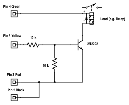
Normally a driver is needed to connect an external load to the Pin 5, This can be a simple general purpose transistor (2N2222) or a Darlington driver IC (ULM2801/2803) like in the following diagrams:
Keep in mind that when you drive a solenoid relays, a protection diode should be used. If you drive a high voltage solid state relay, be very careful to avoid the hazard of an electric shock.
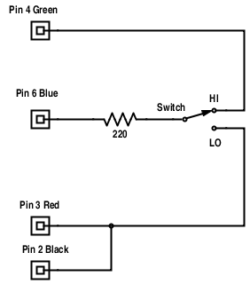
Digital input
DIGI1 - Pin 6 can be used as a general purpose digital input. To get the current state, use the isPressed() method of the TouchSensor class. The LOW - HIGH threshold is about 2.5 V. Insert a 2.2 kOhm serial resistor to protect the input (max input voltage 5 V).
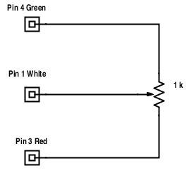
Analog input
AN - Pin 1 can be used as a general purpose analog input. You get the raw input voltage like a NXT light sensor (class NxtLightSensor). The input voltage 0..5 V is converted with a 10 bit analog-digital converter. The reported light sensor raw value is 1023 for 0 V and 0 for 5 V because the input is inverted. Keep in mind that the input impedance is low (pull-up resistor 10 kOhm). You can make a simple test circuit using a potentiometer of about 1 kOhm and connect as follows:
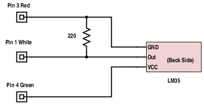
Temperature sensor
Already for the Lego RCX system, an thermistor based temperature sensor was available. Apparently the sensor uses a R25 = 10 kOhm thermistor with a 2.2 kOhm resistor in series. It can be connected directly between the Pin 3 - Red and the Pin 1 - White ports. When data are read as NxtLightSensor, the raw value reading is about 900 at -20 °C and 260 at 70 °C with little non-linearity.
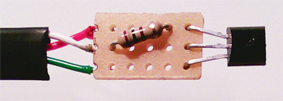
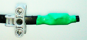
It is easy to build a home-brew temperature sensor based on the LM35 chip family. These 3 wire sensors outputs a voltage that corresponds directly to the measured temperature with 10 mV/deg. So at 0 °C the output voltage is 0 V and at 100 °C the voltage is 1 V. Because of the internal pull-up resistor of the EV3 analog input, a pull-down resistor of about 220 Ohm must be inserted. The mechanical construction is up to you, below some suggestions using a shrink-on tube to protect the sensor when immerged into a liquid.
Much more accurate is the NXT temperature sensor (9749) that is supported in the EV3JLib in autonomous and direct mode by the class TemperatureSensor.
The raw value must be converted to the temperature using a linear relationship:
| T (°C) |
U (Volt) |
v (raw value) |
| 0 |
0 |
1023 |
| 100 |
1 |
818 |
which gives T = (1023 - v) / k with k = 2.05. In praxis more accurate values are obtained for k = 2.2. The following programs in Java and Python display the temperature on the EV3 screen. They run in autonomous or direct mode.
import ch.aplu.ev3.*;
public class TempLM35
{
public TempLM35()
{
LegoRobot robot = newLegoRobot();
NxtLightSensor ls =
new NxtLightSensor(SensorPort.S1);
robot.addPart(ls);
while (!robot.isEscapeHit())
{
int v = ls.getValue();
double T = (1023 - v) / 2.2;
T =(int)(10 * T) / 10.0;
System.out.println("T = "+ T);
Tools.delay(1000);
}
robot.exit();
}
public static void main(String[] args)
{
new TempLM35();
}
} |
from ev3robot import *
robot = LegoRobot()
ls = NxtLightSensor(SensorPort.S1)
robot.addPart(ls)
while not robot.isEscapeHit():
v = ls.getValue()
T = (1023 - v) / 2.2
T = int(10 * T) / 10.0
robot.drawString("T = " + str(T), 0, 1)
print "T =", T, "degrees"
Tools.delay(1000)
robot.exit()
|
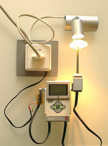
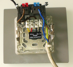
A demonstration of a typical control loop: Stabilizing the temperature
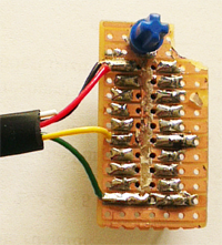
This example is the prototype of a control loop in a feedback control system. To maintain a given nominal temperature TNominal at a certain location heated by a 50 W halogen lamp, the lamp is turned off, when the current temperature T is greater than TNominal (T > TNominal) and turned on, when T is smaller or equals TNominal (T <= TNomial). To switch the high voltage for the lamp (110 V or 230 V), care must be taken to avoid electric hazards. For security reasons a solid state relay (SSR) is build into an external boxed plug socket, so that the high voltage part is completely separated from the low voltage electronic circuitry. Because the maximum drive capacity of the EV3 digital output is very small, it cannot switch the SSR directly. But it is easy to obtain the necessary drive current by using a Darlington array IC mounted on a small circuit board (see the schematics above). Only 4 wires from the EV3 sensor cable are used: black (pin 2) and red (pin 3) wired together for the ground, green (pin 4) for VCC und yellow (pin 5) for the digital output.
The program uses the NxtLightSensor class to activate/deactivate the digital output at DIGI0 and either the TemperatureSensor class to read the temperature of the Lego NXT temperature sensor (see Java program) or the NxtLightSensor class to get the raw values of a LM35 based homebrew temperature sensor (see the Python program) can be used. As you see the program logic is extremely simple. Again the same programs can be run in autonomous or direct (remote) mode.
// TempControl.java
import ch.aplu.ev3.*;
public class TempControl
{
private final double TNominal = 60;
public TempControl()
{
LegoRobot r = new LegoRobot();
NxtLightSensor heater =
new NxtLightSensor(SensorPort.S1);
r.addPart(heater);
TemperatureSensor temp =
new TemperatureSensor(SensorPort.S4);
r.addPart(temp);
boolean activated = false;
while (!r.isEscapeHit())
{
double T = temp.getTemperature();
// System.out.println("T = " + T + " deg.");
r.drawString("T = " + T + " deg.", 1, 1);
if (T > TNominal && activated)
{
heater.activate(false);
activated = false;
// System.out.println("Off");
r.drawString("Off", 1, 2);
}
if (T <= TNominal && !activated)
{
heater.activate(true);
activated = true;
// System.out.println("On");
r.drawString("On", 1, 2);
}
Tools.delay(1000);
}
r.exit();
}
public static void main(String[] args)
{
new TempControl();
}
}
|
# TempControl.py
from ev3robot import *
TNominal = 50 # degrees Celsius

r = LegoRobot()
heater = NxtLightSensor(SensorPort.S1)
r.addPart(heater)
temp = NxtLightSensor(SensorPort.S4)
r.addPart(temp)
activated = False
while not r.isEscapeHit():
    v = temp.getValue()
    T = (1023 - v) / 2.2
    T = int(10 * T) / 10.0
    print "T = " + str(T) + " deg."
    r.drawString("T = " + str(T), 1, 1)
    if T > TNominal and activated:
        heater.activate(False)
        activated = False
        print "Off"
        r.drawString("Off", 1, 2)
    if T <= TNominal and not activated:
        heater.activate(True)
        activated = True
        print "On"
        r.drawString("On", 1, 2)
    Tools.delay(1000)
r.exit()
|
Using I2C Expanders
The I2C protocol is widely used to interface microprocessor based systems to digital or analog I/O devices. Only three wires are needed: Ground (GND), Serial Clock Line (SCL) and Serial Data Line (SDA). The EV3 acts as a I2C master and up to 128 external I2C slaves can be connected to a single EV3 sensor port, but most of the time only one slave is connected to a sensor port. The master selects the slave by sending an I2C address byte. The following bytes are data or control bytes sent from the master to the slave (WRITE mode) or from the slave to the master (READ mode).
The lack of a general GPIO interface with the EV3 can be easily overcome by attaching as sensor one of the well-known I2C expander ICs, like the PCF8574/PCF8574A for digital I/O and the PCF8591 for analog I/O. Only two pull-up resistors are necessary as additional components. The expander ICs can be build with your own test or soldering board. Expander kits are also available (e.g. from mindsensors.com). The basic circuitry is the following:
|
|
|
|
PCF8574/PCF8574A Digital I/O
|
PCF8591 Analog I/O
|
A Demonstration for Digital I/O
|
Since the PCF8574/PCF8574A can pull-down up to 10 mA per output pin, LEDs or a LED array with serial resistors connected to VCC may be directly driven. The test layout uses a LED array, switches and 8 pull-up resistors of 270 Ohm. P0 and P1 may be used as input. To do so, a logical 1 must be written into the corresponding port bits. The expander than reports the current state of all port bits, so a logical 1, if the switch is open and 0, if the switch is closed.
Your demonstration program defines bits #0 and #1 as inputs and counts up in bit #2 to bit #7. It then displays what is received from the two input bits. If you press the switches, the corresponding bits are read as logical 0.
|
 |
The program code is shown in Java and Python. Again It runs in autonomous or direct (remote) mode.
import ch.aplu.ev3.*;
public class PCF8574Demo
{
private static final int deviceType = 1; // PCF8574A
private static final int i2CSlaveAddress = 0x70; // PCF8574A
// private static final int i2CSlaveAddress = 0x40; // PCF8574
public PCF8574Demo()
{
LegoRobot robot = new LegoRobot();
robot.drawString("PCF8574Demo", 0, 0);
I2CExpander i2C = new I2CExpander(
SensorPort.S1, deviceType, i2CSlaveAddress);
robot.addPart(i2C);
int count = 0;
while (!robot.isEscapeHit())
{
int out = 0x03;
out = out + (count << 2);
int reply = i2C.writeDigital(out);
System.out.println("got: " + (reply & 0x03));
count += 1;
Tools.delay(100);
}
robot.exit();
}
public static void main(String[] args)
{
new PCF8574Demo();
}
} |
from ev3robot import *

deviceType = 1 # PCF8574A
i2CSlaveAddress = 0x70 # PCF8574A
# i2CSlaveAddress = 0x40 # PCF8574

robot = LegoRobot()
robot.drawString("PCF8574Demo", 0, 0)
i2C = I2CExpander(SensorPort.S1,
         deviceType, i2CSlaveAddress)
robot.addPart(i2C)
count = 0
while not robot.isEscapeHit():
    out = 0x03
    out = out + (count << 2)
    reply = i2C.writeDigital(out)
    robot.drawString("got: " +
      str(reply & 0x03), 0, 2)
    print "got: ", reply & 0x03
    count += 1
    Tools.delay(100)
robot.exit()
|
A Demonstration for Analog I/O
|
The PC8591 I2C Expander has 4 analog inputs and 1 analog output, all of them 8-bit wide only. The inputs can be connected in different modes (single ended, differential or mixed). Consult the datasheet for more information. The impedances of the digital inputs are about 50 kOhm and the digital output should not be loaded with less than 10 kOhm.
For the demonstration, a single potentiometer of about 1 kOhm is connected to analog channel 0 input. The digitized voltage is displayed on the EV3 display and converted to a sound frequency that is played as repetitive tone.
|
|
The program code is shown in Java and Python. Again It runs in autonomous or direct (remote) mode.
import ch.aplu.ev3.*;
public class PCF8591Demo
{
private static final int deviceType = 2;
private static final int i2CSlaveAddress = 0x90;
private int channel = 0;
public PCF8591Demo()
{
LegoRobot robot = new LegoRobot();
robot.drawString("PCF8591Demo", 0, 0);
I2CExpander i2C = new I2CExpander(
SensorPort.S1, deviceType, i2CSlaveAddress);
robot.addPart(i2C);
while (!robot.isEscapeHit())
{
int v = i2C.readAnalog(channel);
int f = 500 + 10 * v;
robot.drawString("v: " + v, 0, 1);
robot.drawString("f: " + f + " Hz", 0, 2);
robot.playTone(f, 100);
}
robot.exit();
}
public static void main(String[] args)
{
new PCF8591Demo();
}
} |
from ev3robot import *
deviceType = 2 # PCF8591
i2CSlaveAddress = 0x90
channel = 0

robot = LegoRobot()
robot.drawString("PCF8591Demo", 0, 0)
i2C = I2CExpander(SensorPort.S1,
         deviceType, i2CSlaveAddress)
robot.addPart(i2C)
while not robot.isEscapeHit():
    v = i2C.readAnalog(channel)
    f = 500 + 10 * v
    robot.drawString("v: " + str(v), 0, 1)
    robot.drawString("f: " + str(f) + " Hz", 0, 2)
    print "f: ", f, "Hz"
    robot.playTone(f, 100)
robot.exit()
|
There is a distinct difference in the repetition rate of the tone for the Java and Python programs that let you compare the execution speed. Of course the winner is Java in autonomous mode.
Consult the Java documentation for more information about class I2CExpander constructor parameters and methods.
| |
 LinkUp
 TCPCom
 Simulations