| |
The source code of all experiments is included in the NxtJLibA distribution.
Ninth example: NXT to control Hitechnic SuperPro Prototype Board
(NxtJLibA autonomous mode)
Purpose: Use the NXT brick as a controller for the Hitechnic SuperPro Prototype Board
HiTechnic (http://www.hitechnic.com) provides a Superpro Experimenter's Kit that contains the Superpro Prototype Board, a solderless experimental breadboard and some elementary electronic devices like LEDs, button switches, resistors, a capacitor, a transistor and some special sensors for temperature and magnetic field. In the SuperPro Experimenter's Kit Handbook that can be downloaded from their web site, a couple of experiments are explained in full details. So even people with no experience in electronics are capable to build the electronic circuits easily and operate them successfully. Constructing electronic circuits and drive them by a self-programmed microcontroller is a very modern and fascinating activity. The HiTechnic hardware and the accompanying tutorials are valuable contributions to the teaching of electronic engineering.
The choice of the programming language for the microcontroller is not of great importance, because the fundamental thinking to drive the electronic gear remains the same for all languages. Normally the program starts with a initializing phase and then loops for reading sensor data or user input and transferring data to electronic actors or a display according to a simple algorithm specific for the experimental purpose. This corresponds clearly to the fundamental input-process-output (IPO-) model.
The SuperPro Prototype Board is a replacement of the older NXT Solderless Prototype Board used in the NxtJLib Examples 5. All experiments and programs can be easily adapted to the new hardware since the methods of class PrototypeSensor and class SuperProSensor are almost the same. The new board has 4 analog outputs (0..3.3V, 10bit), 8 digital inputs/outputs (0 / 3.3V), 2 analog outputs (frequency 1..8191 Hz, 0..3.3V, modes: DC, sine wave, square wave, positive sawtooth, negative sawtooth, triangle wave, pulse width modulation), 4 strobe outputs (general digital outputs), a WR strobe output (rectangle pulse of approx. 0.5 us length (3V approx.) at every write action to digital out (B0..B7 ports) and ad RD strobe output (rectangle pulse of approx. 0.5 us length (3V approx.) at every
read action of digital in (B0..B7) ports).
The Experimenter's Kit Handbook (that can be downloaded from HiTechnic's web site) describes a couple of experiences in details. All these experiments can also be driven by Java programs downloaded to the Lego NXT brick running the leJOS firmware. The following experiment descriptions are extracted from the HiTechnic Handbook, where you find more detailed information (© Dataport Systems, Inc, HiTechnic Division 2011).
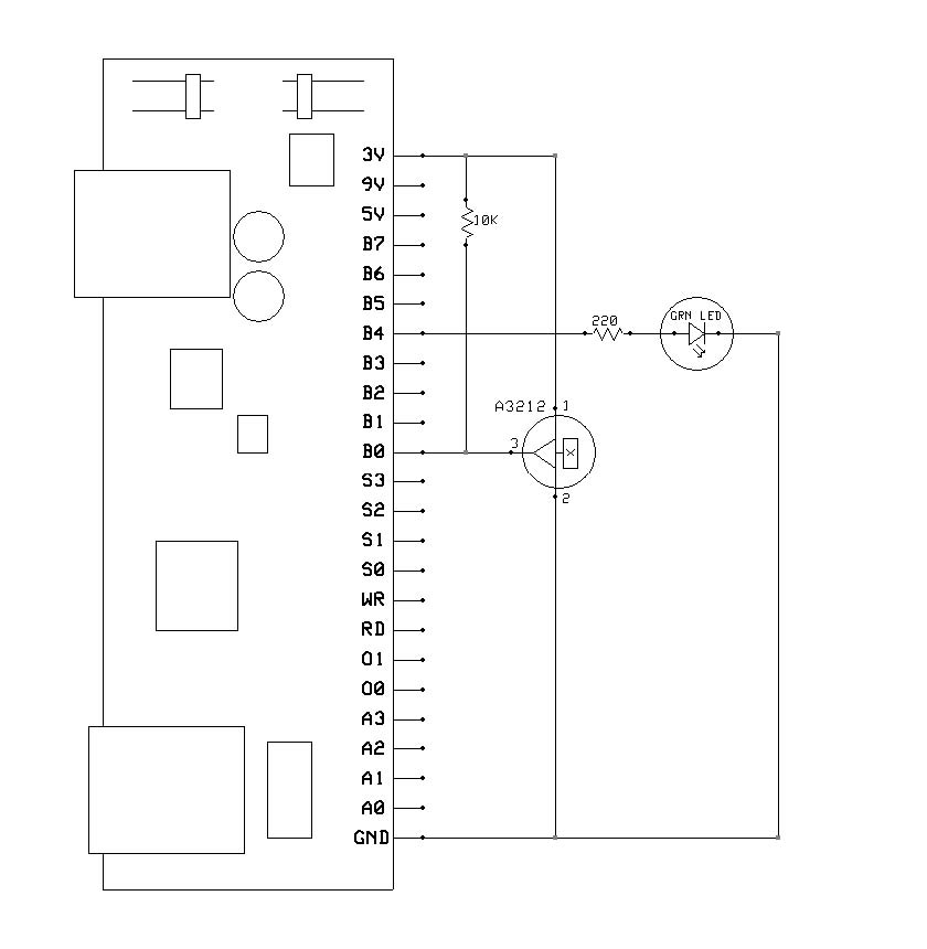
Experiment - 1 Introduction to the SuperPro
This experiment will introduce you to the HiTechnic SuperPro and techniques to create circuits.
With this experiment you will build a simple circuit with a switch and one LED. The NXT program for this circuit reads the status of the switch and when it is closed (the switch is pressed), the program will power the LED.
Schematic diagram:
Programming:
This test program will read the voltage across the 10K ohm resistor and turns the LED on if this voltage is greater than half the maximum possible voltage. When you press the switch, the NXT program will turn the LED on by writing a 1 to the digital output port.
/* HiTechnic Experimenter's Kit Program
Experiment - 1 Introduction - Read the status of a switch and display the status on a LED
(c) HiTechnic 2009
*/
// Adapted to Java by Aegidius Pluess (www.aplu.ch)
import ch.aplu.nxt.*;
import lejos.nxt.LCD;
public class SuperProExp1
{
private final int out = 1;
public SuperProExp1()
{
NxtRobot robot = new NxtRobot();
SuperProSensor sps = new SuperProSensor(SensorPort.S1);
robot.addPart(sps);
int[] dout = new int[8];
int[] ain = new int[4];
int[] ioControl = {out, out, out, out, out, out, out, out};
sps.setDIO(ioControl);
while (true)
{
sps.readAnalog(ain);
LCD.clear();
LCD.drawInt(ain[0], 0, 0);
if (ain[0] < 512)
dout[0] = 0;
else
dout[0] = 1;
sps.write(dout);
Tools.delay(50);
}
}
public static void main(String[] args)
{
new SuperProExp1();
}
}
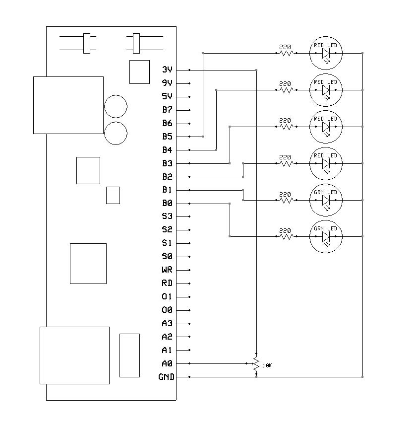
Experiment - 2 Six LEDs and a potentiometer
This experiment demonstrates how to read an analog device, in this case a variable potentiometer, and output a digital value that is used to drive 6 LEDs.

Programming:
The program reads the analog port A0 to read the voltage from the potentiometer and uses this value to decide which LED to turn on. The LEDs are turned on by writing the correct value to the digital port.
As you turn the potentiometer clockwise, you’ll notice that the LEDs turn on in sequence. This sequence has been made deliberately non-linear. Non-linear means that the voltage levels at which each LED turns on are not equally spaced.
/* HiTechnic Experimenter's Kit Program
Experiment - 2 Six LEFs and a Potentiometer
This program reads the analog value of a potentiometer and outputs a
digital value to one of six LEDs.
(c) HiTechnic 2009
*/
// Adapted to Java by Aegidius Pluess (www.aplu.ch)
import ch.aplu.nxt.*;
import lejos.nxt.LCD;
public class SuperProExp2
{
private final int out = 1;
public SuperProExp2()
{
NxtRobot robot = new NxtRobot();
SuperProSensor sps = new SuperProSensor(SensorPort.S1);
robot.addPart(sps);
int dout;
int[] ain = new int[4];
int[] ioControl = {out, out, out, out, out, out, out, out};
sps.setDIO(ioControl);
while (true)
{
sps.readAnalog(ain);
LCD.clear();
LCD.drawInt(ain[0], 0, 0);
dout = 0x01;
if (ain[0] > 31)
dout = 0x02;
if (ain[0] > 63)
dout = 0x04;
if (ain[0] > 127)
dout = 0x08;
if (ain[0] > 255)
dout = 0x10;
if (ain[0] > 511)
dout = 0x20;
sps.write(dout);
Tools.delay(50);
}
}
public static void main(String[] args)
{
new SuperProExp2();
}
}
Experiment - 3 Six LEDs and a microphone
This experiment will use the same layout as Experiment 2 plus the NXT sound sensor instead of the potentiometer.
Programming:
The program reads the sound level from the sound sensor and turns all LEDs on based on the measurement from the sound sensor like a LED array sound indicator (from left to right).
/* HiTechnic Experimenter's Kit Program
Experiment - 3 Six LEDs and a the sound sensor
This program reads the raw value of the sound sensor and outputs a
digital value to one of six LEDs.
Port 1 - HiTechnic Prototype Board
Port 2 - Sound sensor
(c) HiTechnic 2009
*/
// Adapted to Java by Aegidius Pluess (www.aplu.ch)
// Modifications: LEDs used as line indicator
import ch.aplu.nxt.*;
import lejos.nxt.LCD;
public class SuperProExp3
{
private final int out = 1;
public SuperProExp3()
{
NxtRobot robot = new NxtRobot();
SoundSensor ss = new SoundSensor(SensorPort.S2);
robot.addPart(ss);
SuperProSensor sps = new SuperProSensor(SensorPort.S1);
robot.addPart(sps);
int dout;
int[] ain = new int[4];
int[] ioControl = {out, out, out, out, out, out, out, out};
sps.setDIO(ioControl);
int soundlevel;
while (true)
{
soundlevel = ss.getValue();
LCD.clear();
LCD.drawInt(soundlevel, 0, 0);
dout = 0x01;
if (soundlevel > 6)
dout += 0x02;
if (soundlevel > 30)
dout += 0x04;
if (soundlevel > 50)
dout += 0x08;
if (soundlevel > 70)
dout += 0x10;
if (soundlevel > 90)
dout += 0x20;
sps.write(dout);
Tools.delay(50);
}
}
public static void main(String[] args)
{
new SuperProExp3();
}
}
Experiment - 4 Light Level
This experiment shows you how to build a working light sensor.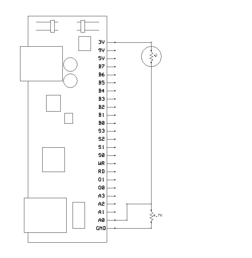
Programming:
The program reads the voltage from the photocell and displays it on the NXT screen.
As you allow more light to shine on the photocell, the higher the reading will be.
/* HiTechnic Experimenter's Kit Program
Experiment - 4 Light Level sensor
This program reads the analog value from a photo cell and displays the light level.
(c) HiTechnic 2009
*/
// Adapted to Java by Aegidius Pluess (www.aplu.ch)
import ch.aplu.nxt.*;
import lejos.nxt.LCD;
public class SuperProExp4
{
private final int out = 1;
public SuperProExp4()
{
NxtRobot robot = new NxtRobot();
SuperProSensor sps = new SuperProSensor(SensorPort.S1);
robot.addPart(sps);
int dout;
int[] ain = new int[4];
while (true)
{
sps.readAnalog(ain);
LCD.clear();
LCD.drawInt(ain[0], 0, 0);
Tools.delay(50);
}
}
public static void main(String[] args)
{
new SuperProExp4();
}
}
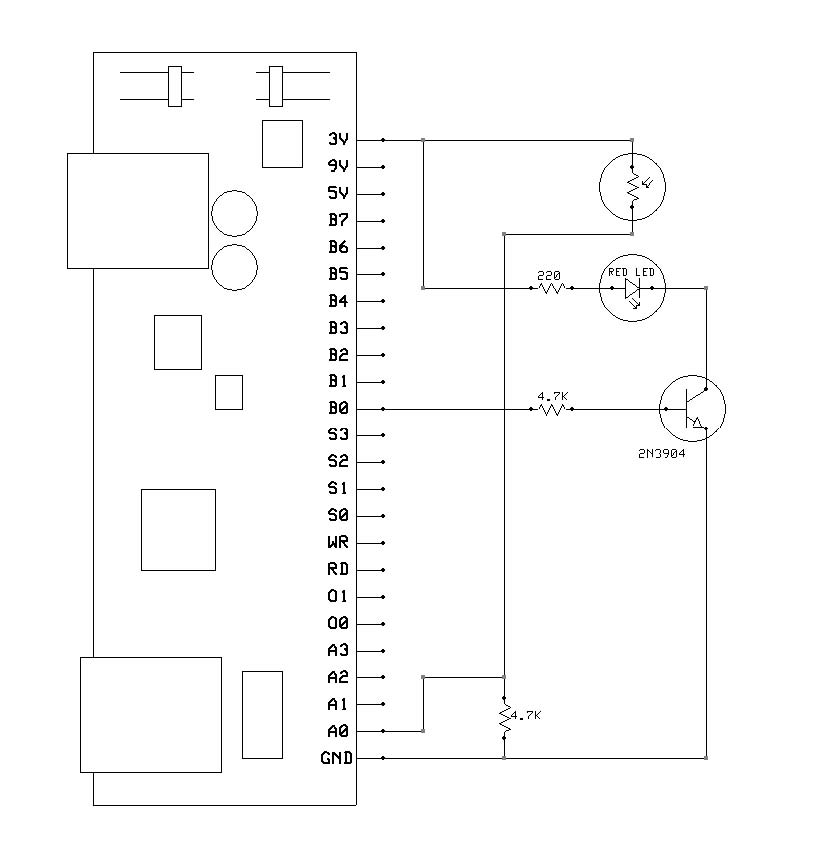
Experiment - 5 Ambient Canceling Light Sensor
This experiment uses the layout built in Experiment 4 and adds to the design by creating a light sensor that measures and cancels out the background light level.
Programming:
The program turns the LED on and off and measures the light level for both conditions. It then subtracts the reading obtained with the LED off from the reading obtained with the LED on and displays that value. If there is nothing placed above the LED – photocell sensor head, these readings will be very similar. However, if a white object or surface is placed a few centimeters above the sensor head, the two readings will start to differ because the white surface reflects the light from the LED when it is on. This provides a good way to detect the presence or absence of an object.
You can experiment to see how different colored and different sized objects affect the results.
/* HiTechnic Experimenter's Kit Program
Experiment 5 - Ambient Canceling Light Sensor
This program reads the light level with a reference light source on and also off,
calculates the background light level to create an ambient (background) canceling light sensor.
(c) HiTechnic 2009
*/
// Adapted to Java by Aegidius Pluess (www.aplu.ch)
import ch.aplu.nxt.*;
import lejos.nxt.LCD;
public class SuperProExp5
{
private final int out = 1;
public SuperProExp5()
{
NxtRobot robot = new NxtRobot();
SuperProSensor sps = new SuperProSensor(SensorPort.S1);
robot.addPart(sps);
int dout;
int[] ain = new int[4];
int[] ioControl = {out, out, out, out, out, out, out, out};
sps.setDIO(ioControl);
int wolight, wlight, lightdelta;
while (true)
{
sps.readAnalog(ain); // Measure light off
wolight = ain[0]; // Save
sps.write(0x01); // Turn light on
Tools.delay(30); // Wait
sps.readAnalog(ain); // Measure light on
wlight = ain[0]; // Save
sps.write(0); // Turn light off
lightdelta = wlight - wolight; // Calculate difference
LCD.clear(); // Show result
LCD.drawInt(wlight, 0, 0);
LCD.drawInt(wolight, 0, 1);
LCD.drawInt(lightdelta, 0, 2); // Changes if high reflection
Tools.delay(30);
}
}
public static void main(String[] args)
{
new SuperProExp5();
}
}
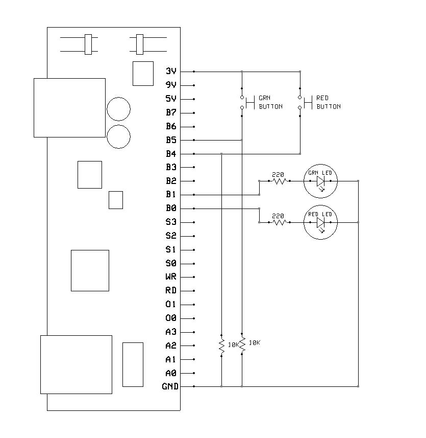
Experiment - 6 Reaction Time Measurement
This experiment will allow you to build a simple reaction timer to measure the time it takes you to press a button after a light has been turned on.
Programming:
The program waits for a random amount of time and then turns on the red LED as well as starting a timer. When the red button is then pressed, the timer is stopped and the number of milliseconds it took to press the button is displayed in milliseconds (a millisecond is 1/1000 of a second).
To restart the test, press both the red and green buttons at the same time.
/* HiTechnic Experimenter's Kit Program
Experiment - 6 Reaction Time Measurement
This program measures the time taken to press a button switch after a LED is turned on.
(c) HiTechnic 2009
*/
// Adapted to Java by Aegidius Pluess (www.aplu.ch)
import ch.aplu.nxt.*;
import lejos.nxt.LCD;
public class SuperProExp6
{
private final int in = 0;
private final int out = 1;
public SuperProExp6()
{
NxtRobot robot = new NxtRobot();
SuperProSensor sps = new SuperProSensor(SensorPort.S1);
robot.addPart(sps);
int[] din = new int[8];
int[] ioControl = {out, out, out, out, in, in, out, out};
sps.setDIO(ioControl);
int randomtime;
while (true)
{
sps.write(0);
LCD.clear();
LCD.drawString("running", 0, 0);
randomtime = (int)(5000 * Math.random()) + 5000;
Tools.delay(randomtime);
sps.write(0x01);
Tools.startTimer();
do
{
sps.readDigital(din);
}
while (din[4] == 0);
sps.write(0);
LCD.clear();
LCD.drawInt((int)Tools.getTime(), 0, 0);
do
{
sps.readDigital(din);
}
while (din[4] == 0 || din[5] == 0);
}
}
public static void main(String[] args)
{
new SuperProExp6();
}
}
Variant - More Complex Reaction Time Measurement
A variant of this experiment uses the same layout but will require a more complex response.
The program waits for a random amount of time and then randomly turns on either the red or green LED as well as starting a timer. When the matching button is then pressed, the timer is stopped and output as the number of milliseconds it took for the subject to press it after seeing the LED turn on.
This test adds a decision to the reaction time measurement which for most subjects will add to their reaction time.
To restart the test, press both the red and green buttons at the same time.
/* HiTechnic Experimenter's Kit Program
Experiment - 6 Reaction Time Measurement
This program measures the time taken to press a button switch after a LED is turned on.
(c) HiTechnic 2009
*/
// Adapted to Java by Aegidius Pluess (www.aplu.ch)
import ch.aplu.nxt.*;
import lejos.nxt.LCD;
public class SuperProExp6Var
{
private final int in = 0;
private final int out = 1;
public SuperProExp6Var()
{
NxtRobot robot = new NxtRobot();
SuperProSensor sps = new SuperProSensor(SensorPort.S1);
robot.addPart(sps);
int[] din = new int[8];
int[] ioControl = {out, out, out, out, in, in, out, out};
sps.setDIO(ioControl);
int randomtime;
int buttonindex;
int outputmask;
while (true)
{
sps.write(0);
LCD.clear();
LCD.drawString("running", 0, 0);
if (Math.random() < 0.5)
{
outputmask = 0x01;
buttonindex = 4;
}
else
{
outputmask = 0x02;
buttonindex = 5;
}
randomtime = (int)(5000 * Math.random()) + 5000;
Tools.delay(randomtime);
sps.write(outputmask);
Tools.startTimer();
do
{
sps.readDigital(din);
}
while (din[buttonindex] == 0);
sps.write(0);
LCD.clear();
LCD.drawInt((int)Tools.getTime(), 0, 0);
do
{
sps.readDigital(din);
}
while (din[4] == 0 || din[5] == 0);
}
}
public static void main(String[] args)
{
new SuperProExp6Var();
}
}
Experiment - 7 Magnetic Switch Sensor
This experiment shows you how to build a working magnetic switch sensor.
Programming:
The program reads the output from the magnetic sensor and uses it to turn the LED on or off.
Use the supplied HiTechnic magnet to activate the magnetic sensor.
/* HiTechnic Experimenter's Kit Program
Experiment - 7 Magnetic Switch Sensor
This program measures reads the status of the magnetic sensor and outputs the status.
(c) HiTechnic 2009
*/
// Adapted to Java by Aegidius Pluess (www.aplu.ch)
import ch.aplu.nxt.*;
import lejos.nxt.LCD;
public class SuperProExp7
{
private final int in = 0;
private final int out = 1;
public SuperProExp7()
{
NxtRobot robot = new NxtRobot();
SuperProSensor sps = new SuperProSensor(SensorPort.S1);
robot.addPart(sps);
int[] din = new int[8];
int[] ioControl = {in, out, out, out, out, out, out, out};
sps.setDIO(ioControl);
while (true)
{
LCD.clear();
sps.readDigital(din);
if (din[0] == 0)
{
LCD.drawString("Magnet present", 0, 0);
sps.write(0x10);
}
else
{
LCD.drawString("Magnet absent", 0, 0);
sps.write(0);
}
Tools.delay(50);
}
}
public static void main(String[] args)
{
new SuperProExp7();
}
}
Experiment - 8 Temperature Sensor
This experiment will allow you to build a working temperature sensor
.
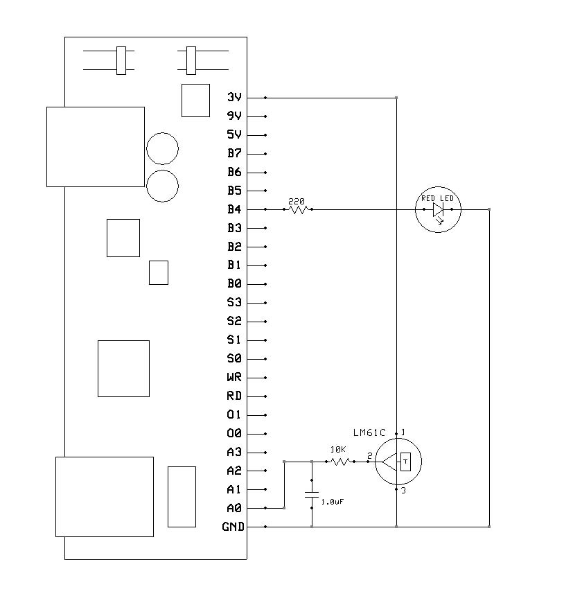
Programming:
The program reads the voltage from the temperature sensor and coverts it to degrees Celsius and then displays it. It also decides if it is above a predefined threshold and if so turns the LED on.
/* HiTechnic Experimenter's Kit Program
Experiment - 8 Temperature Sensor
This program reads the temperature sensor and displays the value.
(c) HiTechnic 2009
*/
// Adapted to Java by Aegidius Pluess (www.aplu.ch)
import ch.aplu.nxt.*;
import lejos.nxt.LCD;
public class SuperProExp8
{
private final int out = 1;
private final int threshold = 24; // Degrees centigrade
public SuperProExp8()
{
NxtRobot robot = new NxtRobot();
SuperProSensor sps = new SuperProSensor(SensorPort.S1);
robot.addPart(sps);
int[] ain = new int[4];
int[] ioControl = {out, out, out, out, out, out, out, out};
sps.setDIO(ioControl);
int temperature;
while (true)
{
sps.readAnalog(ain);
temperature = ((ain[0] - 186) * 32) / 99;
LCD.clear();
LCD.drawInt(temperature, 0, 0);
if (temperature > threshold)
sps.write(0x10);
else
sps.write(0);
Tools.delay(50);
}
}
public static void main(String[] args)
{
new SuperProExp8();
}
}
Experiment - 9 Speaker output
This experiment shows you how to use the speaker and create different sounds and musical notes from your test programs.
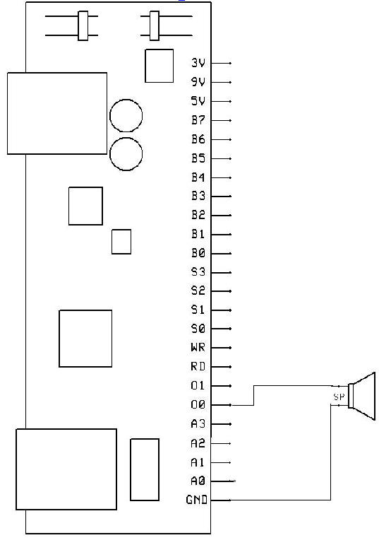
Programming:
The program plays a sequence of three ascending notes
Experiment - 10 Morse code generator (not part of the HiTechnic Handbook)
This experiment uses the same layout as experiment 9. It plays a arbitrary text in Morse code. The Morse code consists of dots (short beeps called dits) and dashes (longer beeps called dashs.) The dash is 3 times longer than the dot and there is a pause lasting the same time as one dot between beeps in the character and a pause lasting as one dash between characters. The pause between words should last 7 dots.
(By adding a solid state relay or a reed contact, you could use the NXT as CW keyer for a ham transmitter.)
Programming:
Two test sequences are hard coded. The code is stored in a HashMap (partial, may be completed).
import ch.aplu.nxt.*;
import java.util.*;
public class SuperProMorse
{
private Hashtable<Character, String> code = new Hashtable<Character, String>();
private final int dot = 60; // ms
private SuperProSensor sps = new SuperProSensor(SensorPort.S1);
public SuperProMorse()
{
NxtRobot robot = new NxtRobot();
robot.addPart(sps);
populateCode();
// play("abcdefghijklmnopqrstuvwxyz1234567890");
play("cq cq de hb9abh cq cq de hb9abh pse k");
robot.exit();
}
void play(String s)
{
for (int i = 0; i < s.length(); i++)
{
char ch = s.charAt(i);
System.out.print(ch);
String pattern = code.get(ch);
playPattern(pattern);
}
}
void populateCode()
{
code.put(' ', " ");
code.put('a', ".-");
code.put('b', "-...");
code.put('c', "-.-.");
code.put('d', "-..");
code.put('e', ".");
code.put('f', "..-.");
code.put('g', "--.");
code.put('h', "....");
code.put('i', "..");
code.put('j', ".---");
code.put('k', "-.-");
code.put('l', ".-..");
code.put('m', "--");
code.put('n', "-.");
code.put('o', "---");
code.put('p', ".--.");
code.put('q', "--.-");
code.put('r', ".-.");
code.put('s', "...");
code.put('t', "-");
code.put('u', "..-");
code.put('v', "...-");
code.put('w', ".--");
code.put('x', "-..-");
code.put('y', "-.--");
code.put('z', "--..");
code.put('1', ".----");
code.put('2', "..---");
code.put('3', "...--");
code.put('4', "....-");
code.put('5', ".....");
code.put('6', "-....");
code.put('7', "--...");
code.put('8', "---..");
code.put('9', "----.");
code.put('0', "-----");
}
void playPattern(String pattern)
{
if (pattern.equals(" "))
{
wordPause();
return;
}
for (int i = 0; i < pattern.length(); i++)
{
char ch = pattern.charAt(i);
if (ch == '.')
dit();
if (ch == '-')
dah();
}
charPause();
}
void dit()
{
sps.setAnalogOut(0, 3, 1000, 1023);
Tools.delay(dot);
sps.setAnalogOut(0, 3, 1000, 0);
Tools.delay(dot);
}
void dah()
{
sps.setAnalogOut(0, 3, 1000, 1023);
Tools.delay(3 * dot);
sps.setAnalogOut(0, 3, 1000, 0);
Tools.delay(dot);
}
void charPause()
{
Tools.delay(3 * dot);
}
void wordPause()
{
Tools.delay(7 * dot);
}
public static void main(String[] args)
{
new SuperProMorse();
}
}
| |
 LinkUp
 TCPCom
 Simulations