|
For Arduino (Uno and others) Pin A4 is used as SDA and Pin A5 as SCL. Since the Arduino is a 5V microcontroller, care should be taken when connecting a 3.3V subsystem. With I²C there's no problem if the internal Arduino's pullup (to the 5V rail) are disabled. This requires a patch to the Wire library (see Internet resources for information). Using the standard library with pullups enabled, a clean hardware configuration would require a bidirectional 5V-to-3.3V converter such as the BSS138 or AN97055 (also available on small breakout boards).
With the ESP32 a direct connection can be established (at your risk), since the ESP32 obvouisly uses clamping diodes on its IO pins and the internal pullups on the Arduino are quite large (approx. 50kOhm). Oscilloscope measurements show that the signal level on SDA/SCL is limited to about 3.3V when the ESP32 is connected.
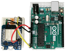
Direct connection using a breadboard (example):
|
|
|
 |
 |
|
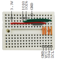
4 cables, GND, SDA-A4, SCL-A5, VCC-5V
|
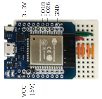
LinkUp inserted into small breadboard
|
Breadboard wiring
|
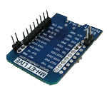
Headers (partially soldered)
|
If you use a breadboard, do not solder the full dual pin header strip into the ESP board since it would shorten pairs of pins.
To power the system, you can connect the 5V pins of the two boards and power the Arduino as usual. The ESP32 will then be powered by the Arduino via this 5V connection. Theoretically, the ESP32 could also be powered by connecting the 3.3V pins, but this fails due to the current limitation of Arduino's 3.3V supply. Attention: Never connect 3.3V and 5V power pins as this will destroy the system.
|
 LinkUp
 TCPCom
 Simulations