| |
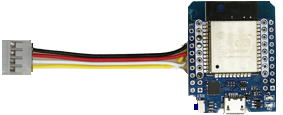
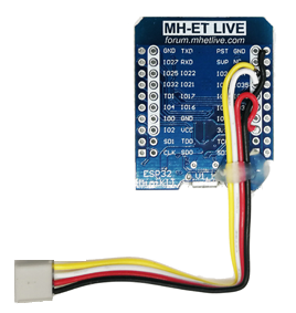
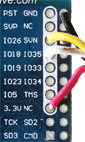
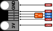
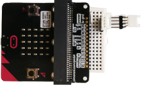
For the connection between the micro:bit and the ESP32 the pins GND, 3.3V, IO18 and IO26 (as SDA and SCL) are used. (The pin definition for SDA and SCL may be changed by patching the LinkManager source.). A simple wiring is to use Grove compatible I²C connections and solder a Grove cable to these pins and connect it to an I²C hub.
| The connection to the micro:bit is made via pins 3v3 19(SCL), P20(SDA) and GND. Several breakout boards and connecter devices are available, such as Pimoroni's pin:bit, Didel's mbHub and Seed's Grove Shield. |
|
Different I2C connector systems:
 |
 |
 |
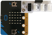
| pin:bit with bread board and Grove connector (www.pimoroni.com) |
Didel mbHub
(www.didel.ch) |
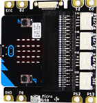
Grove Shield for micro:bit
(www.seedstudio.com) |
Since the 3.3V rails of the micro:bit and the LinkUp are connected via the I2C cable, the entire system can be powered via the micro-USB connector of the ESP32. Powering the micro:bit only does not work due to the output current limitation of the micro:bit (the ESP32 consumes up to 300 mA for WLAN communication).
|
|
 LinkUp
 TCPCom
 Simulations