| |
The source code of all examples can be downloaded from a link in the right side bar.
In almost all applications sensors translate a measurement of a certain physical quantity to a analog voltage. In order to read the value by a computer, the voltage must be converted to a digit in a electronic circuit called a Analog Digital Converter (ADC). The micro:bit has a build-in ADC with a resolution of 10 bits, thus translating an input voltage between 0 and 3.3 V to a number in the range 0..1023. There are 6 input channels on P0, P1, P2, P3, P4 and P10, but only P0, P1 and P2 are freely available. (The other pins are shared with the LED display and may be used, if the display is deactivated by display.off().)
| |

|
Example 1: Measure erratic voltage
|
| |
Aim:
A voltage is a physical quantity measured in an electric field between two points or between one point and a well-defined reference point, e.g. GND. Your finger has a certain erratic voltage with respect to GND because of electric fields present in your surroundings. Measure this voltage every 100 ms and display its value and a time stamp in the terminal.
Program:
# DataAcquisition.py

from microbit import *

t = 0
while True:
    v = pin0.read_analog()
    print(str(t) + ":" + str(v))
    t += 0.1
    sleep(100)
|
Remarks:
The voltage is much fluctuating between 200 and 800 (digital units). |
| |
|
Example 2: Show happy face when P0 is touched |
| |
Aim:
Use your knowledge from the example above to show the image of a happy face, when pin P0 is touched and the image of a sad face, when P0 is left alone.
Program:
# HappyFace.py

from microbit import *

while True:
    v = pin0.read_analog()
    if v > 400:
        display.show(Image.HAPPY)
    else:
        display.show(Image.SAD)
    sleep(100)
|
Remarks:
Because of the fluctuating voltage, a delay of 100 ms is necessary. |
| |
|
Example 3: Simulate sensor with a potentiometer
|
| |
Aim:
If you connect the end taps of potentiometer to GND and VCC and the middle tap to P0, the input voltage at P0 can be varied form 0 to 3.3 V by turning the potentiometer knob. Since the voltage is limited to the maximum input range, this is a more secure arrangement than using an external power supply, where you easily break your micro:bit by applying more than 3.3V or a voltage with inverse polarity.
Program:
(Use DataAcquisition.py from Example 1)
Remarks:
This arrangement with a potentiometer is used to simulate sensor output and test data acquisition in many circumstances.
|
| |
|
Example 4: Dim a LED using PWM
|
| |
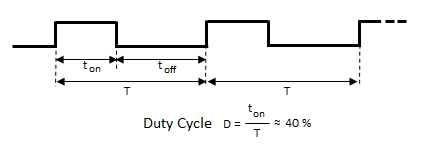
A pulse-width modulated signal is a generalized square-wave, where on and off times ton and toff are not of equal length. It is still a repetitive signal with frequency f = 1 / T (T: period). The duty cycle is the ratio of the on time to the full period and may be expressed in percent.
PWM signals are frequently used to control the mean power of devices such as DC motors, LEDs, etc., but also to select the position of a servo motors. To set the duty cycle, use write_analog(duty) with duty in the range 0..1023. You can't use more than 3 pins for PWM at the same time due to the limitation of processing power. The period of the PWM signal can be changed with write_analog_period(period) with a minimum value auf 1 (1 ms) or set_analog_period_microseconds(period) with a minimum value auf 256 (256 us). The default value is about 20 ms (50 Hz) which is appropriate for many applications.
Aim:
Connect a LED to pin0 and increase its luminosity from zero to maximum and back to zero in an endless loop, until the program is halted by pressing the B button.
Program:
# PWMDimmer.py

from microbit import *

duty = 0
upward = True
while not button_b.was_pressed():
    pin8.write_analog(duty)
    if upward:
        duty += 10
        if duty == 1020:
            upward = False
    else:
        duty -= 10
        if duty == 0:
            upward = True
    sleep(10)
pin8.write_digital(0)
|
Remarks:
To turn off the power completely, it is better to call write_digital(0) then write_analog(0).
You will learn how to change the speed of a DC motor using PWM in the Buggy / Roboter chapter. |
|
|
 LinkUp
 TCPCom
 Simulations